
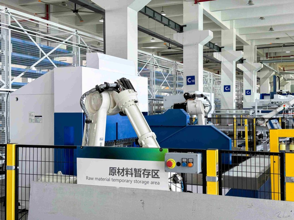
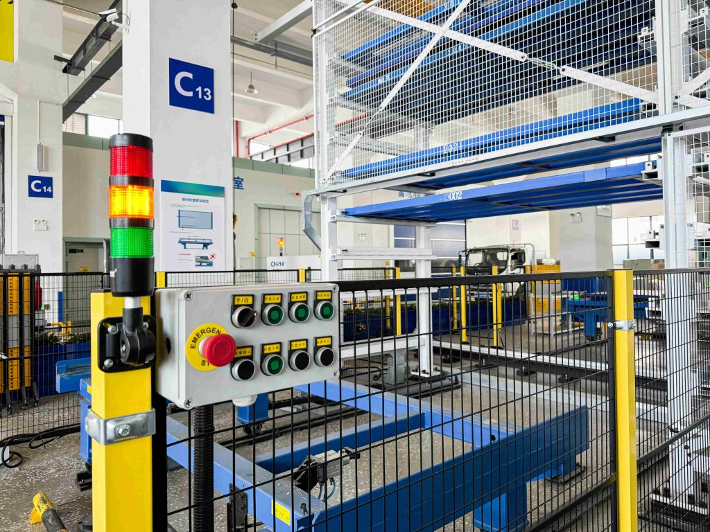
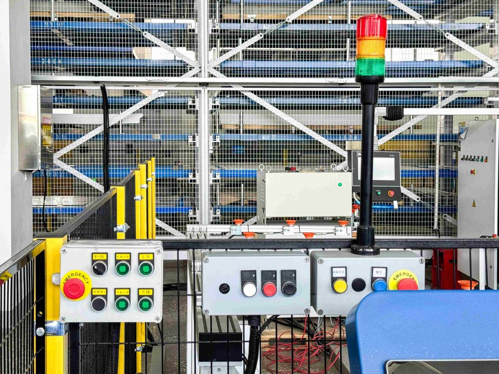
In 2026, an automated manufacturing facility in Jiangsu, China, completed a plant-wide installation of industrial pushbutton control stations across its production, material handling and equipment service areas.
The factory used centralized PLC control, HMI panels and main electrical cabinets to manage the overall production process. However, operators and maintenance personnel still required direct machine-side controls for manual adjustment, operating-mode selection, reset, status confirmation and emergency stopping.
Multiple customized pushbutton boxes were therefore installed throughout the factory. Their size, front-panel layout and control functions were matched to the operating requirements of each machine section.
The three control stations shown in this installation represent typical configurations used in one automated equipment area. Similar local control boxes were deployed on conveyors, transfer mechanisms, automated storage equipment, guarded machine cells and maintenance access points across the facility.
Project Overview
| Project location | Jiangsu, China |
|---|---|
| Project period | 2026 |
| Facility type | Automated manufacturing and material handling factory |
| Project scope | Plant-wide local pushbutton control station installation |
| Installed quantity | Multiple customized control stations across production areas |
| Typical applications | Conveyors, transfer units, lifting mechanisms, storage systems and guarded equipment cells |
| Control functions | Manual operation, mode selection, reset, indication and emergency stopping |
| Operating devices | Push buttons, selector switches, pilot lights and emergency-stop buttons |
| Status indication | Local pilot lights and red, amber and green stack lights |
| Mounting positions | Machine guards, equipment frames, operator stations and access areas |
| Cable arrangement | Protective conduits connected to the factory control system |
Why the Factory Needed Local Pushbutton Control Stations
The automated factory already had centralized HMIs for production monitoring, alarm display and system-level control. Main electrical cabinets housed the PLCs, relays, power supplies and other control components.
Centralized control alone was not sufficient for every operating task.
During equipment setup, fault recovery and maintenance, personnel needed to issue commands while directly observing the corresponding mechanism. Returning to the main HMI for every manual movement or reset would separate the operator from the equipment response.
Plant-wide local control stations were installed to provide:
- Automatic and manual operating-mode selection
- Local start, stop, jog and movement commands
- Reset functions after alarms or process interruptions
- Direct control during machine setup and maintenance
- Emergency-stop access from multiple working positions
- Local equipment-status indication
- Clear control identification for different production sections
- Integration with the central PLC and machine safety circuits
- Consistent enclosure and labeling formats throughout the factory
Because the machines performed different functions, the control requirements were not identical at every location. Each pushbutton box was configured according to its connected equipment, operating sequence and available installation space.
Pushbutton Box Configurations Used Across the Factory
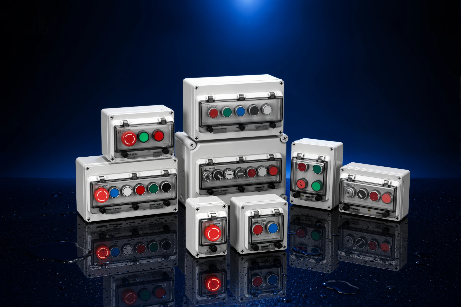
The factory used a family of customized local control stations rather than one fixed button-box layout.
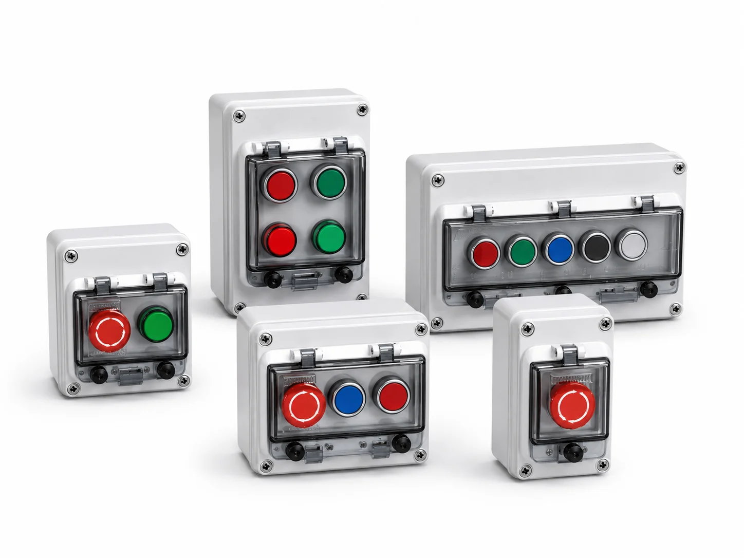
Compact boxes with two or three operators were installed for simple local movements and reset functions. Larger stations combined selector switches, multiple command buttons, indicators and emergency-stop devices for equipment requiring more complex manual control.
Using several enclosure sizes and front-panel layouts allowed the factory to maintain a consistent control-station design while matching the requirements of each production area.
Multi-Function Operator Stations
Larger control stations were installed beside equipment sections requiring several manual commands.
A typical multi-function station combined an automatic/manual selector switch, an emergency-stop button and separate push buttons for equipment movement or position adjustment.
This configuration allowed authorized personnel to select the operating mode and control individual machine movements during setup, maintenance or fault recovery.
The emergency-stop device was placed in a prominent position and visually separated from routine operating controls. Function labels were installed above the selector switch and command buttons so that each operation could be identified before activation.
Compact Local Command Stations
Smaller button boxes were used where operators only needed to control one nearby mechanism or a limited sequence of movements.
These stations typically contained two or three push buttons for functions such as forward and reverse movement, raising and lowering, material positioning or local start and stop.
Removing unnecessary controls from the panel made the relationship between each button and the connected equipment easier to understand.
The compact layout also allowed the boxes to be installed on narrow equipment frames and safety barriers without obstructing access doors or maintenance space.
Reset and Emergency-Stop Stations
Reset and emergency-stop stations were installed at selected operator access points and machine-cell boundaries.
These stations combined a clearly identified reset control with an emergency-stop device and, where required, a pilot light showing the local operating or fault condition.
Separating the reset button from the emergency-stop operator reduced the possibility of selecting the wrong control during fault recovery.
Emergency-stop locations were determined according to the equipment layout, operator positions and machine safety design rather than by using one fixed spacing across the entire plant.
Standardized Control Design Across Production Areas
Although the number and type of operators varied, the factory used a consistent design approach for its local pushbutton stations.
Common enclosure structures, button spacing, cable-entry methods and labeling formats helped create a uniform control system across different equipment areas.
Typical installation locations included:
- Automated conveyor and transfer sections
- Material lifting and lowering equipment
- Automated storage and retrieval systems
- Loading and unloading positions
- Guarded robotic or mechanical cells
- Inspection and positioning stations
- Maintenance and manual-control points
- Emergency-stop access locations
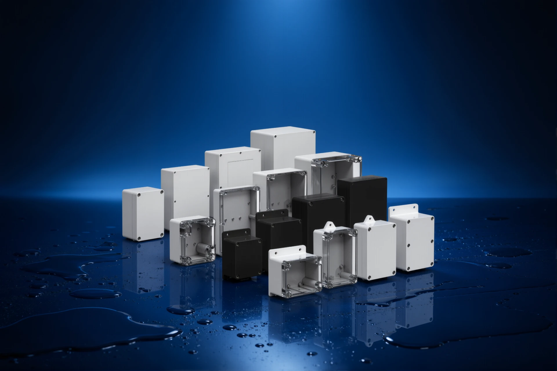
Standardizing the enclosure platform reduced unnecessary variation while still allowing the front-panel layout to be customized for each machine function.
It also made replacement planning easier because stations with similar operating requirements could use the same enclosure size, opening dimensions and mounting arrangement.
Installation Highlights
Machine-Side Mounting
The pushbutton control stations were mounted close to the machine sections they controlled.
Most boxes were installed on the outside of safety barriers, equipment frames or dedicated operator supports. This allowed personnel to issue commands while remaining outside guarded operating areas.
The mounting height and orientation were selected so that buttons, selectors and indicators remained visible and easy to reach from the normal working position.
Controls Positioned Near Their Equipment
Each control station was assigned to the machine section nearest its mounting point.
This distributed arrangement allowed operators to observe the connected mechanism while issuing a manual movement, reset or mode-selection command.
It also reduced confusion between controls serving different conveyors, transfer units or storage mechanisms.
Accessible Emergency-Stop Devices
Emergency-stop buttons were installed in visible and unobstructed positions around operator stations, access areas and machine-cell boundaries.
The red mushroom-head operators and yellow identification backgrounds distinguished the emergency controls from standard push buttons and selector switches.
The emergency-stop devices were integrated into the machine safety circuits according to the factory’s equipment design and risk assessment.
Bottom Cable Entry and Protected Routing
Control cables were routed through protective conduits connected to the lower sections of the button boxes.
Bottom cable entry kept conduits away from the front operating surfaces and created a direct route toward the machine wiring system.
The flexible conduits provided additional mechanical protection where cables passed beside safety barriers, equipment frames and maintenance areas.
Clear Function Labels
Each push button, selector switch and indicator was provided with a visible function label.
The labeling format remained consistent across the factory, making it easier for operators to recognize common commands such as manual, automatic, reset, forward, reverse, raise, lower and emergency stop.
Clear labels also helped maintenance personnel compare the physical controls with electrical drawings, PLC input lists and machine documentation.
Status Indication Across the Factory
Local pilot lights and elevated stack lights were used to communicate equipment status at different viewing distances.
Pilot lights on the button boxes provided information directly at the operating position. Stack lights mounted above selected control stations allowed machine conditions to be recognized from other areas of the workshop.
The factory used red, amber and green indications for common operating states:
- Green: Equipment operating or ready for production
- Amber: Waiting, warning or operator attention required
- Red: Fault, alarm or stopped condition
The exact light sequence was matched to the PLC program and alarm philosophy of each machine section.
Project Result
The completed installation created a network of local control points throughout the automated factory.
Operators can now perform manual movements, mode selection, reset and status checks beside the relevant equipment instead of relying only on centralized HMIs and electrical cabinets.
Maintenance personnel can test individual functions while directly observing the machine response. This is particularly useful during equipment setup, sensor adjustment, fault recovery and scheduled maintenance.
Emergency-stop devices are distributed across production and access areas according to the machine safety layout. Local pilot lights and stack lights provide equipment-status information at both operator and workshop level.
Different button-box configurations allow each production section to receive only the controls required for its operating sequence. Compact stations support simple local functions, while larger multi-operator boxes provide mode selection, movement commands, indication and emergency stopping.
The consistent enclosure style, function labels and cable-routing methods also provide a more organized factory installation and support future replacement or production-line expansion.
Key Benefits of the Plant-Wide Installation
- Distributed local control: Operators can issue commands while observing the corresponding equipment.
- Flexible configurations: Each button box is matched to the machine function and operating sequence.
- Accessible emergency stopping: Emergency-stop devices are positioned across machine cells and operator areas.
- Clear function grouping: Each station contains only the controls required for its equipment section.
- Consistent factory design: Common enclosure, labeling and cable-entry methods are used across production areas.
- PLC integration: Local buttons, selectors and indicators operate as part of the centralized automation system.
- Improved maintenance access: Equipment can be adjusted and checked without repeated travel to the main cabinet.
- Scalable installation: Additional control stations can be added when new machines or production lines are introduced.
How to Specify Pushbutton Boxes for an Automated Factory
A plant-wide pushbutton box project should begin with a control-station schedule covering every required configuration.
| Specification Item | Information to Provide |
|---|---|
| Station type | Unique reference number for each button-box configuration |
| Enclosure dimensions | Required width, height, depth and available mounting area |
| Operator quantity | Number of push buttons, selectors, indicators and emergency stops |
| Opening diameter | Mounting-hole size required for each control operator |
| Front-panel layout | Operator positions, spacing, rows and orientation |
| Control functions | Start, stop, reset, manual, automatic, jog, direction or movement |
| Internal depth | Space required for contact blocks, terminals and conductor bending |
| Cable entry | Cable quantity, gland or conduit size and required entry position |
| Mounting method | Machine frame, safety guard, wall or standalone support |
| Installation environment | Dust, moisture, vibration, oil mist and cleaning exposure |
| Identification | Printed labels, engraved plates, symbols or custom markings |
| Quantity by type | Required production quantity and spare units for each configuration |
Grouping similar station layouts can simplify enclosure selection, opening preparation, production inspection and future spare-parts management.
Order & Project Support
BOWO pushbutton control station boxes can be used for machinery, pumps, conveyors, production lines and other local equipment-control applications.
Standard and customized configurations can be evaluated according to the enclosure size, operator quantity, opening layout, cable-entry position and internal wiring requirements.
For a factory-wide automation project, provide:
- Control-station schedule
- Required enclosure dimensions
- Dimensioned front-panel drawings
- Button, selector and indicator quantities
- Mounting-hole diameters
- Internal component dimensions
- Cable and conduit sizes
- Required cable-entry positions
- Mounting method for each station
- Installation environment
- Quantity required for each layout
- Spare-unit and packaging requirements
Contact BOWO Electric with your control-station schedule, front-panel drawings or equipment photographs to discuss a suitable pushbutton box configuration.
Frequently Asked Questions
Why does an automated factory need local pushbutton boxes if it already has HMIs?
Local pushbutton boxes allow operators to issue manual commands, reset equipment and access emergency-stop functions beside individual machines. HMIs manage system-level control and production data, while local stations support tasks that require the operator to observe the equipment response directly.
Are all pushbutton boxes in an automated factory configured the same way?
No. Each pushbutton box is configured according to the connected machine and operating sequence. A simple station may contain two or three command buttons, while a larger station may include selector switches, pilot lights, multiple movement controls and an emergency-stop device.
Where are industrial pushbutton control stations installed in a factory?
Industrial pushbutton control stations are commonly installed on machine frames, safety guards, conveyor sections, operator stations, loading areas and maintenance access points. The controls should remain visible and reachable without requiring personnel to enter a hazardous machine area.
How do multiple pushbutton stations connect to a factory PLC?
Push buttons and selector switches normally connect to PLC digital inputs, while pilot lights and status indicators connect to PLC or relay outputs. The PLC processes each signal according to the operating mode, machine sequence, interlocks and permitted conditions.
Can different pushbutton layouts use the same enclosure series?
Yes. A common enclosure series can support several front-panel layouts when the box dimensions, opening spacing and internal depth are suitable. This allows a factory to standardize enclosure construction while customizing the controls for individual machines and production areas.
Project Information for a Similar Application
If your project is similar to this one, send the following and we will confirm the enclosure series and configuration:
- Installation environment
- Enclosure size
- Internal components
- Cable-entry requirements
- Quantity
- Operator count and layout
Product category: Waterproof Push Button Control Stations · Product used: IP66 Push Button Control Station Box · Related application: Industrial Automation & Machinery