
Contents ▴
For a machine builder or automation integrator, the number of positions in a push button control station should be fixed only after the local control functions, operator access and maintenance requirements are clear. Choosing a 3-position or 6-position enclosure first and then forcing the control logic into it usually creates unnecessary compromises.
The practical sequence is: define the local functions, decide which controls must remain physically accessible at the machine, group related operators, then select the enclosure layout.
Start With the Local Control Function List
Before selecting a waterproof push button box, prepare the local operator list for the machine or equipment station.
| Control Function | Typical Operator | Position Impact |
|---|---|---|
| Start / Stop | Push buttons | Usually two positions if both are required locally |
| Reset | Push button | Add one position where local reset is required |
| Manual / Auto | Selector switch | Usually one selector position |
| Status indication | Pilot light | Add only where local indication is useful |
| Emergency stop | E-stop operator | Must be considered separately from ordinary operator layout |
Do not add positions simply because the enclosure has room. Every operator should have a defined machine-control purpose.
Use 1–3 Positions for Simple Local Functions
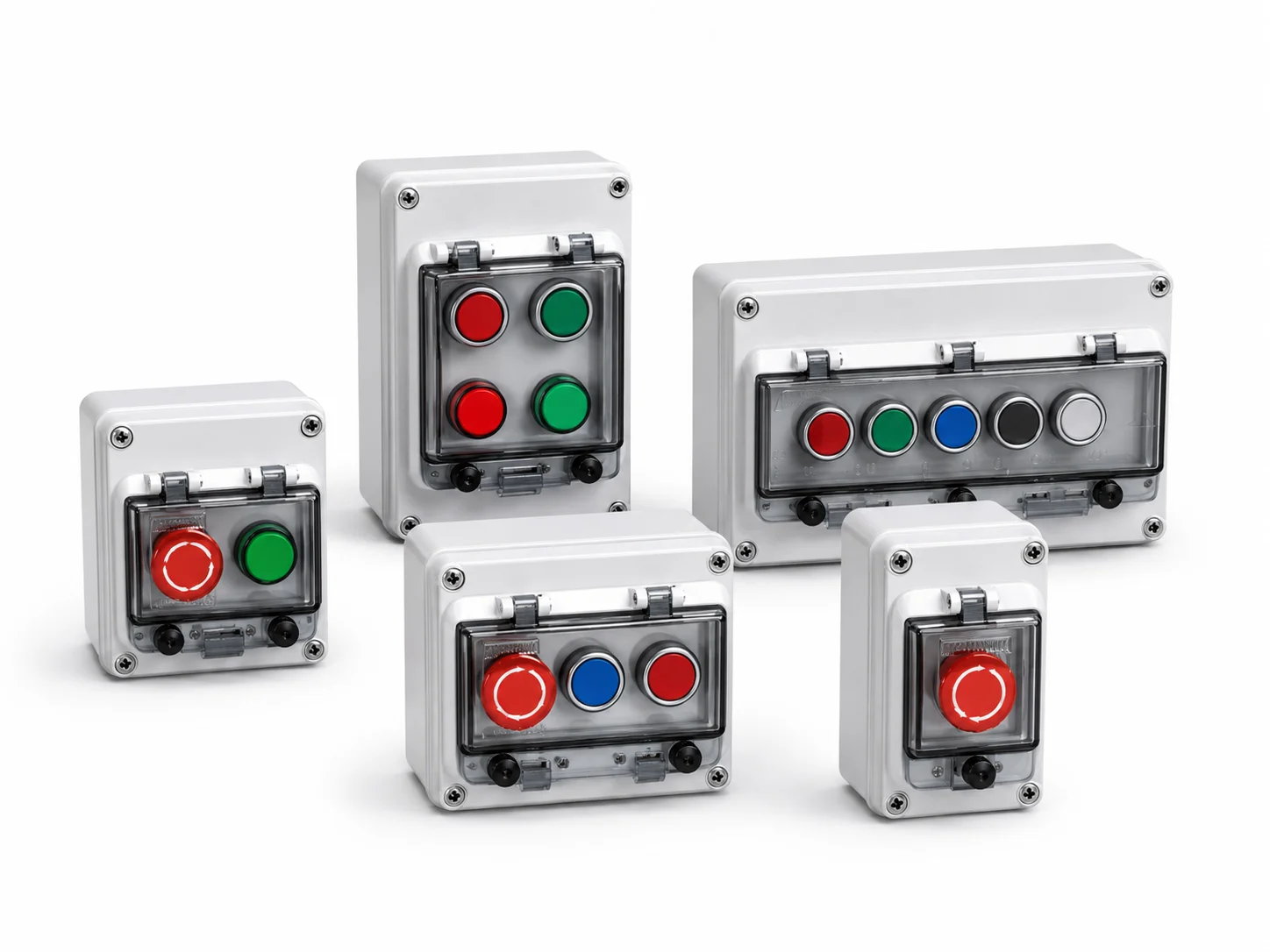
A compact push button station is appropriate when the machine only requires a limited number of local functions. Examples include a single emergency-stop point, a basic start/stop station, or a three-position combination where one additional selector or indicator is required.
The enclosure should still be checked against operator body depth, contact blocks, internal wiring and cable-entry position. Hole count alone is not enough to confirm the box size.
Use 4–7 Positions When Several Local Functions Must Be Grouped
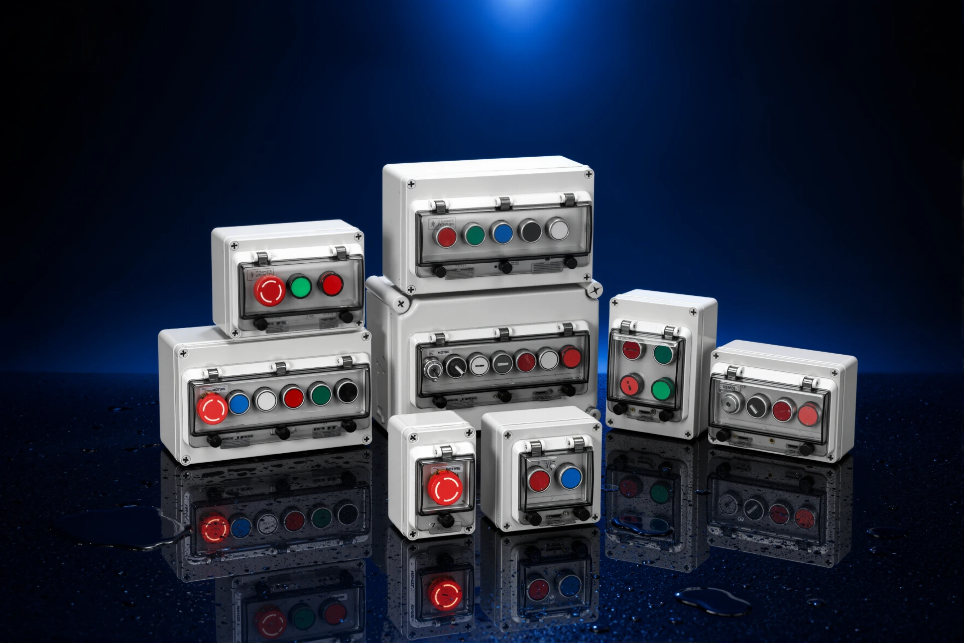
Machine-side stations often expand once start/stop, reset, mode selection, status indication and emergency functions are grouped in one location. BOWO's Button Box range covers configurations from one to seven operator positions, including different multi-position arrangements.
For a larger station, avoid treating the enclosure as a simple row of holes. Group operators according to the sequence in which technicians use them, and leave enough separation for identification, gloved operation and maintenance access.
Single-Row or Double-Row Layout?
Once four or more positions are required, the physical arrangement becomes as important as the total position count.
| Layout | Better Fit |
|---|---|
| Single row | Linear operator sequence, narrow mounting area, simple left-to-right control logic |
| Double row | Several functions that need grouping, limited horizontal space, or clearer separation between command and indication functions |
For repeat OEM machinery, standardizing one operator arrangement across the equipment series can simplify enclosure machining, wiring documentation and spare-part management.
Do Not Treat the Emergency Stop as Just Another Position
An emergency-stop operator should not be positioned only according to visual symmetry or available enclosure space. Its location, accessibility and implementation should follow the machine risk assessment and applicable safety requirements.
From an enclosure standpoint, the RFQ should state clearly whether an E-stop is included so that the operator arrangement and remaining positions can be reviewed correctly.
Check Internal Depth and Cable Entry Before Freezing the Layout
A control station enclosure that has enough front-face positions can still be unsuitable if the internal contact blocks, conductors and cable glands compete for the same space.
- operator body and contact-block depth;
- number of conductors per operator;
- incoming cable direction;
- gland size and internal projection;
- clearance for maintenance tools;
- required bend radius inside the box.
For project-specific layouts, provide the operator positions and cable-entry drawing before machining. BOWO supports custom openings for the Button Box series.
Choose the Cover Configuration With the Operator Layout
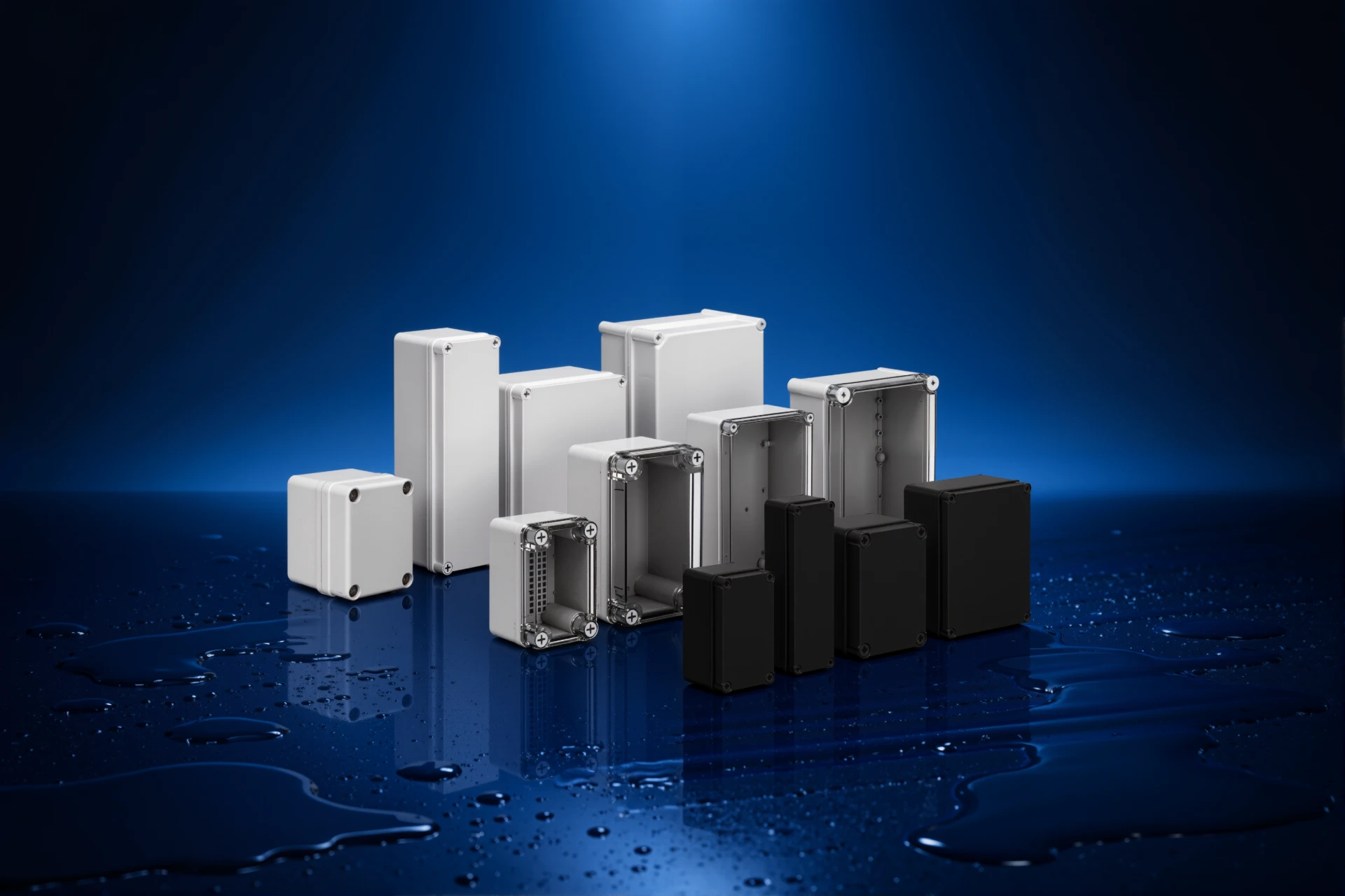
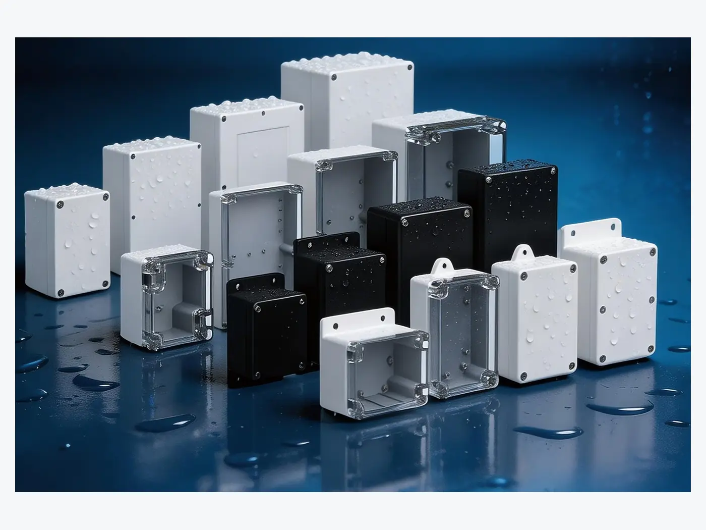
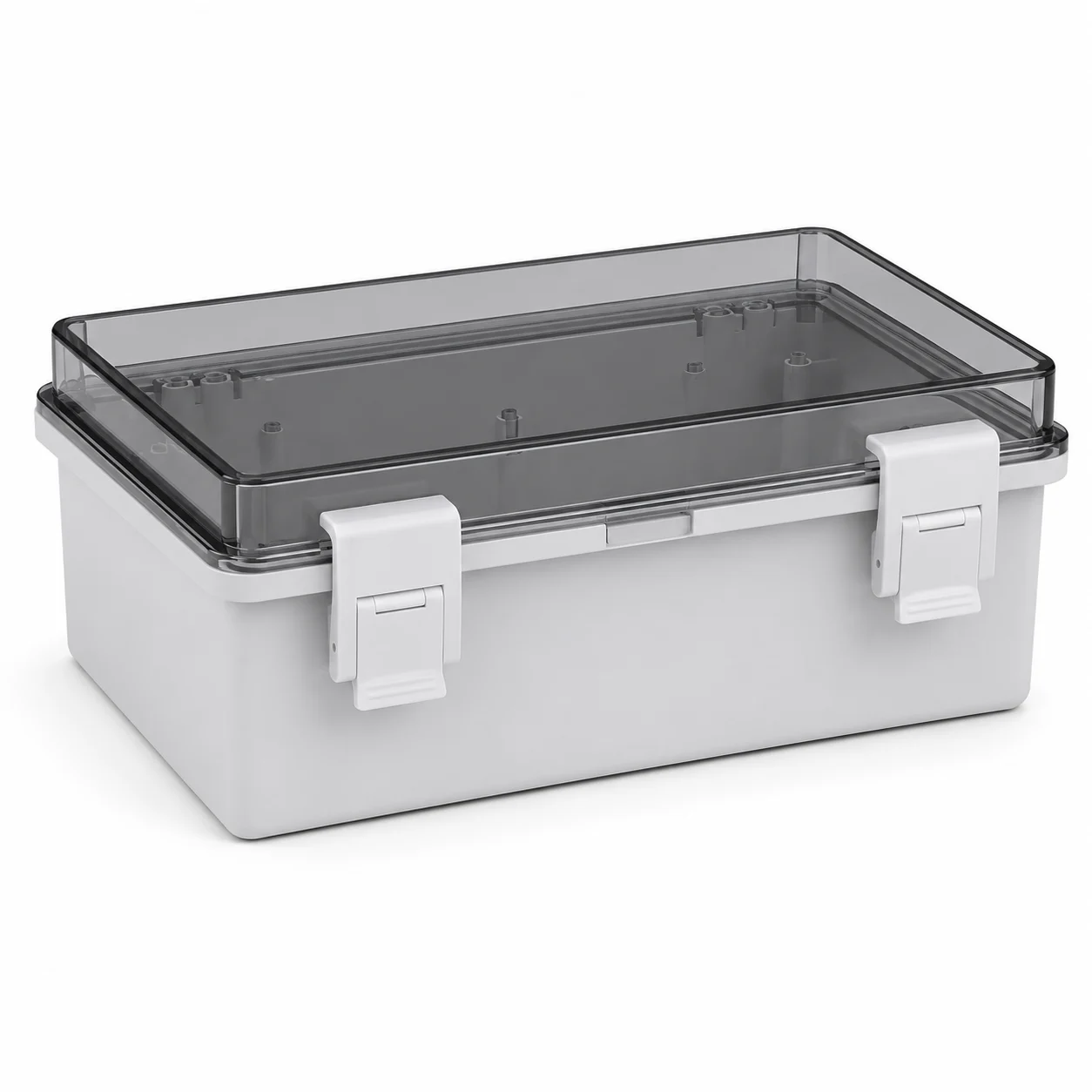
BOWO offers gray and transparent cover configurations for the IP66 push button box series. A transparent protective cover is useful where operators or indicator status need to remain visible while the outer cover is closed. A gray-cover arrangement may be more appropriate where that additional visual access is not required.
The enclosure series is specified as ABS, IP66 and IK08, with CE and RoHS listed in the BOWO catalogue.
RFQ Checklist for a Machine Control Station
| RFQ Item | Information to Provide |
|---|---|
| Machine function | What the local station controls |
| Operator count | Required number of positions |
| Operator type | Push button, selector, pilot light, E-stop |
| Layout | Single row, double row or drawing |
| Cover | Gray or transparent |
| Cable entry | Side, quantity and gland size |
| Environment | Indoor, outdoor, washdown or machine-side conditions |
| Customization | Opening drawing and marking requirements |
| Quantity | Prototype, project batch or repeat OEM quantity |
Standardize the Station Before Releasing the Machine Design
For repeat-production machinery, the best time to define the push button layout is before the enclosure drawing and wiring documentation are released.
BOWO's IP66 Waterproof Push Button Control Station Box range covers 1–7 position configurations and can be matched to gray or transparent cover requirements and custom opening layouts.
For related machine-side enclosure applications, see BOWO's waterproof electrical enclosures for industrial automation and machinery.